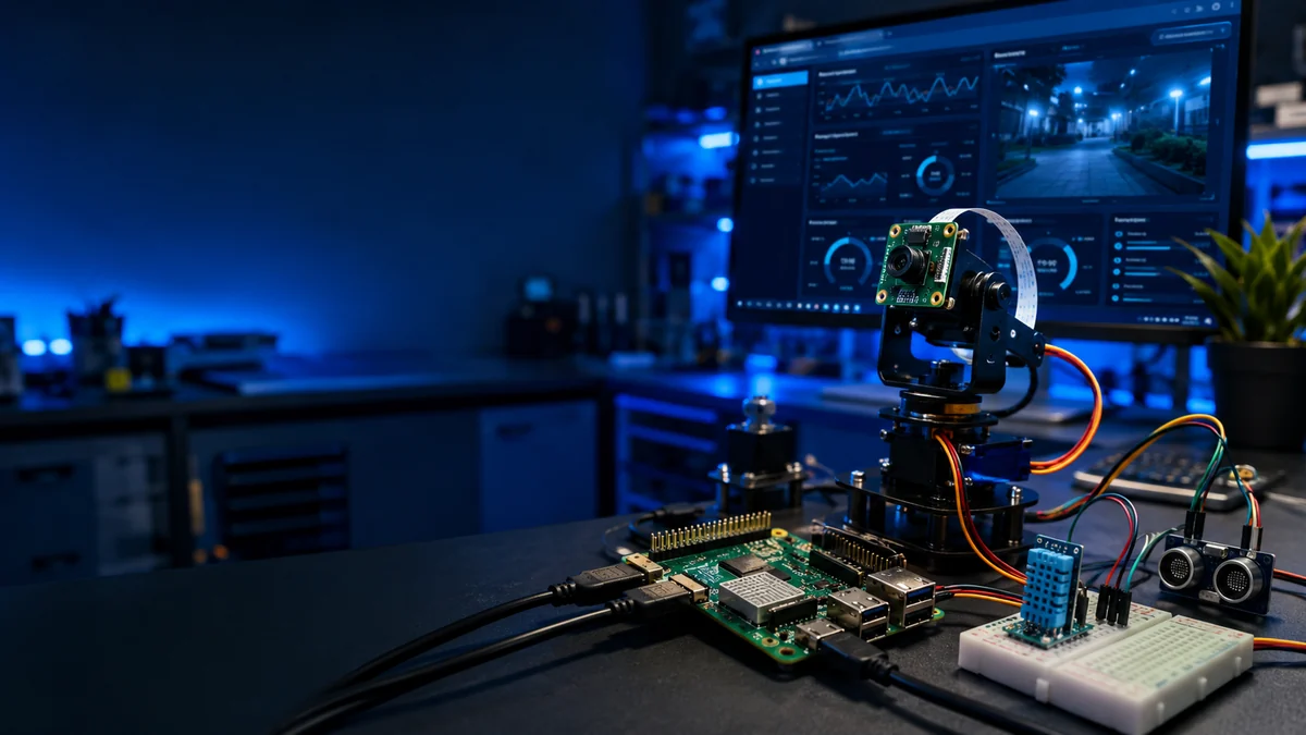
Advanced Tutorial 1 · IntermediateStep 1 of 5 · Browser control and GPIO output
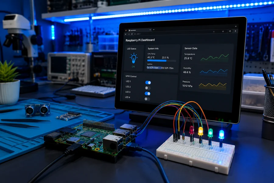
Raspberry Pi Flask Web Dashboard
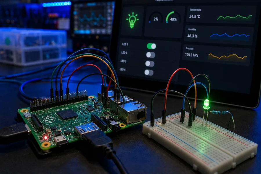
Goal: Build a local browser dashboard that shows Pi status and lets the reader control a GPIO output without touching the Pi directly.
What should happen: A phone, tablet, or desktop on the same Wi-Fi opens the Pi dashboard and turns an LED on and off from the browser.
Printable Flask Lab Manual Included
This upgraded Flask Web Dashboard section now includes a PDF lab manual with GPIO LED wiring, install commands, full Flask code, network testing, troubleshooting, and upgrade paths.
Easy Build Steps
- Wire the LED long leg through a resistor to GPIO17, physical pin 11.
- Connect the LED short leg to a ground pin such as physical pin 6.
- Boot the Pi and run sudo apt update.
- Install Flask and gpiozero with pip3 install flask gpiozero.
- Find your Pi IP address with hostname -I.
Starter Code
from flask import Flask, redirect
from gpiozero import LED
from datetime import datetime

app = Flask(__name__)
led = LED(17)

@app.route('/')
def home():
    state = 'ON' if led.value else 'OFF'
    now = datetime.now().strftime('%Y-%m-%d %H:%M:%S')
    return f'''
    <h1>WolfieWeb Pi Dashboard</h1>
    <p>LED status: <strong>{state}</strong></p>
    <p>Last refresh: {now}</p>
    <a href="/on">Turn LED ON</a> | <a href="/off">Turn LED OFF</a>
    '''

@app.route('/on')
def on():
    led.on()
    return redirect('/')

@app.route('/off')
def off():
    led.off()
    return redirect('/')

app.run(host='0.0.0.0', port=5000)
Quick Test
Run python3 app.py, then open http://PI-IP-ADDRESS:5000 from another device on the same Wi-Fi. If the page loads but the LED does not change, the wiring is wrong.
Upgrade Path
- Add a temperature display card.
- Add buttons for multiple GPIO outputs.
- Add a login before controlling anything important.
✔ Micro-win: Tutorial 1 is still here. This is the Raspberry Pi Flask Web Dashboard build, kept intact.
Advanced Tutorial 2 · IntermediateStep 2 of 5 · Network messages and sensor publishing
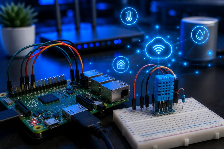
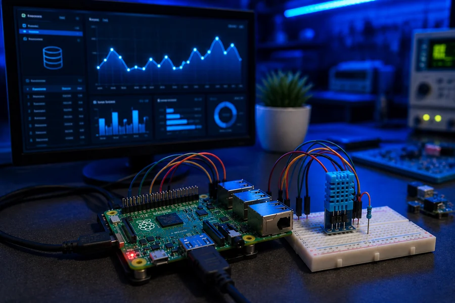
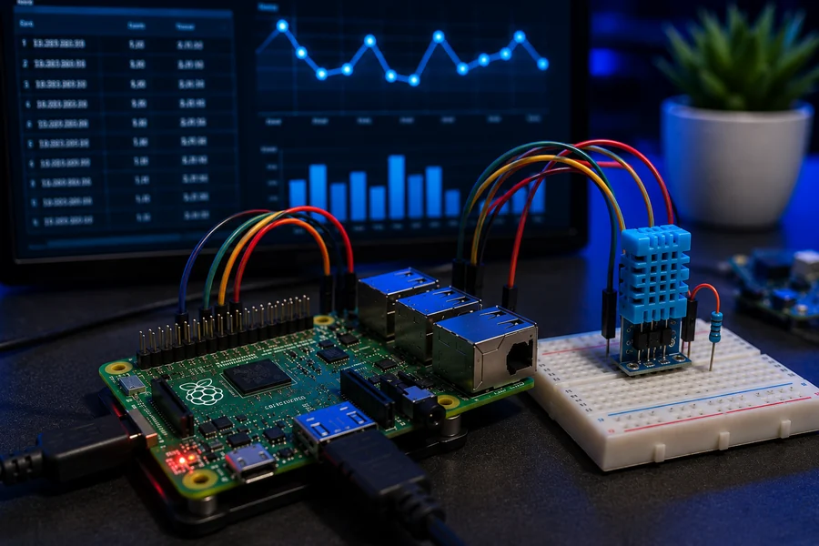
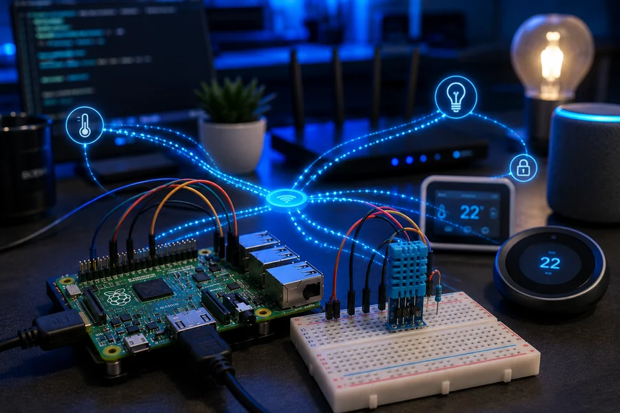
Raspberry Pi MQTT Sensor Hub
Goal: Publish temperature and humidity readings over MQTT so other devices, dashboards, or scripts can react to the Pi.
What should happen: The Pi sends readings to a topic like home/pi/lab every few seconds, and another terminal can subscribe to see them live.
Printable MQTT Lab Manual Included
The upgraded section now includes a printable PDF manual with detailed wiring, install commands, GPIO safety notes, testing steps, and troubleshooting.
Easy Build Steps
- Update the Pi with sudo apt update.
- Install Mosquitto with sudo apt install mosquitto mosquitto-clients -y.
- Enable it at boot with sudo systemctl enable --now mosquitto.
- Wire DHT22 VCC to 3.3V, GND to GND, and DATA to GPIO4.
- Install libraries: pip3 install paho-mqtt adafruit-circuitpython-dht.
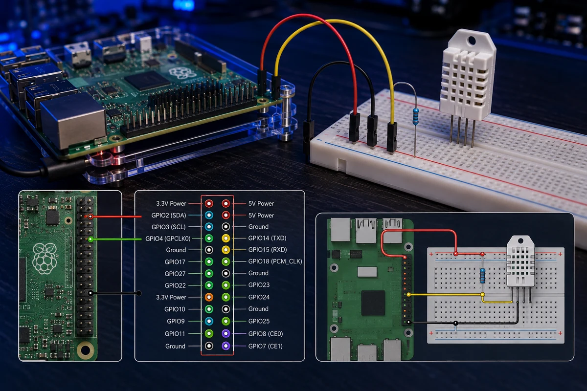
Detailed DHT22 wiring: VCC to 3.3V, DATA to GPIO4, GND to ground, and 10K pull-up resistor between VCC and DATA.
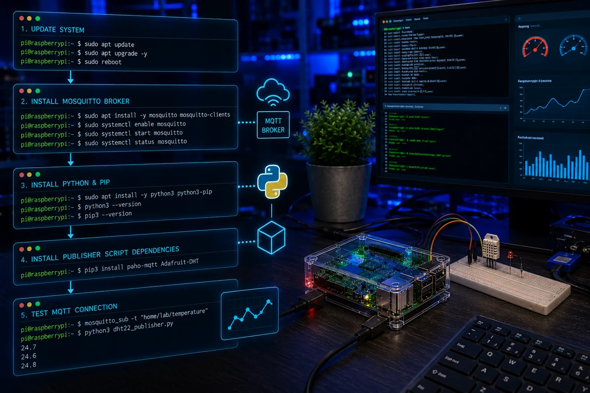
Install flow: update the Pi, install Mosquitto, enable the broker, install Python libraries, then subscribe and test.
Exact Wiring
- DHT22 VCC → Raspberry Pi 3.3V pin.
- DHT22 DATA → Raspberry Pi GPIO4.
- DHT22 GND → Raspberry Pi ground.
- 10K resistor → between VCC and DATA as a pull-up resistor.
Important: Raspberry Pi GPIO pins are 3.3V logic. Do not push 5V into the DATA pin.
Install Commands
sudo apt update
sudo apt install mosquitto mosquitto-clients -y
sudo systemctl enable --now mosquitto
sudo systemctl status mosquitto

pip3 install paho-mqtt adafruit-circuitpython-dht
sudo apt install libgpiod2 -y
Subscriber Test
mosquitto_sub -h localhost -t home/pi/lab
Publisher Code
import time
import board
import adafruit_dht
import paho.mqtt.client as mqtt

sensor = adafruit_dht.DHT22(board.D4)
client = mqtt.Client(mqtt.CallbackAPIVersion.VERSION2)
client.connect('localhost', 1883, 60)

while True:
    try:
        temp = sensor.temperature
        humidity = sensor.humidity
        message = f'temp={temp},humidity={humidity}'
        client.publish('home/pi/lab', message)
        print('Published:', message)
    except RuntimeError as error:
        print('Sensor read failed:', error.args[0])
    time.sleep(5)
Quick Test
In a second terminal, run mosquitto_sub -h localhost -t home/pi/lab. Then start the Python script. If messages appear, the broker and publisher are working.
Upgrade Path
- Subscribe from Node-RED or Home Assistant.
- Send JSON instead of comma text.
- Log MQTT readings into SQLite.
- Push alerts to a dashboard or phone notification system.
Download the Full Wiring & Install Manual
The PDF is included in this ZIP and should be uploaded to /downloads/WolfieWeb_Raspberry_Pi_MQTT_Sensor_Hub_Lab_Manual.pdf.
Open MQTT Sensor Hub PDF✔ Micro-win: Tutorial 2 now has the detailed wiring and installation flow readers need.
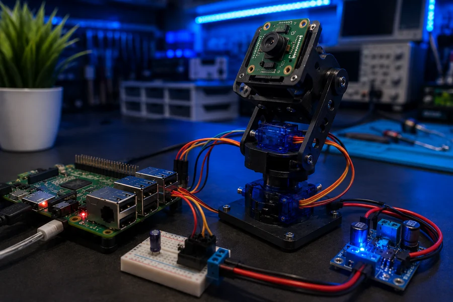
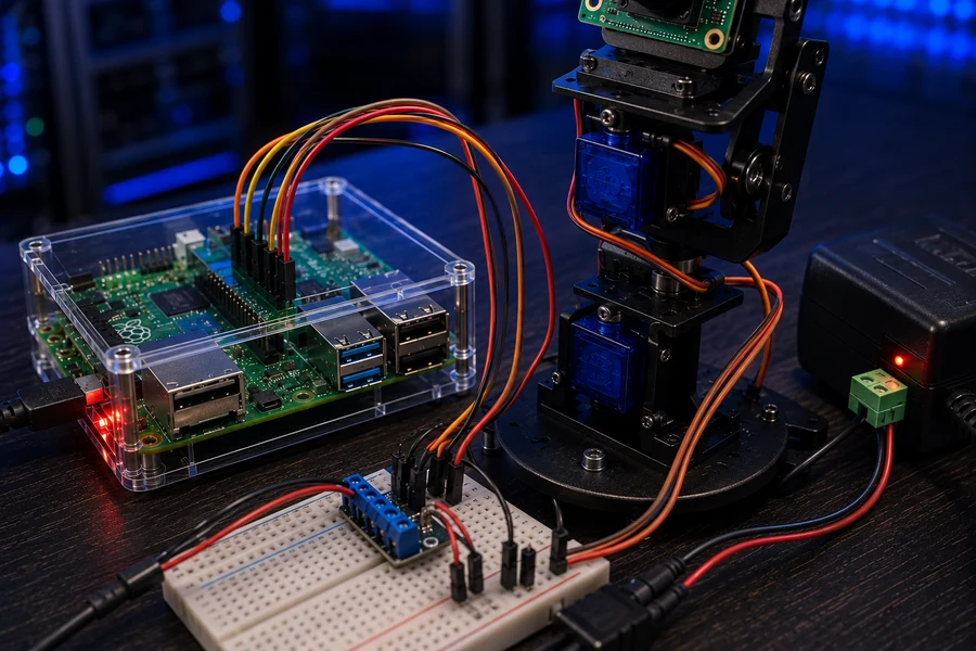
Advanced Tutorial 3 · Intermediate PlusStep 3 of 5 · Computer vision and motion snapshots
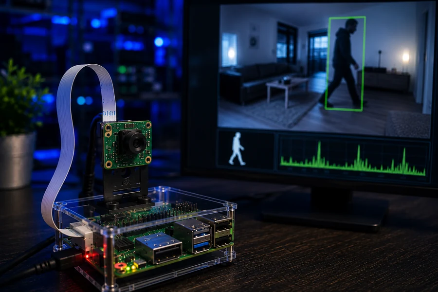
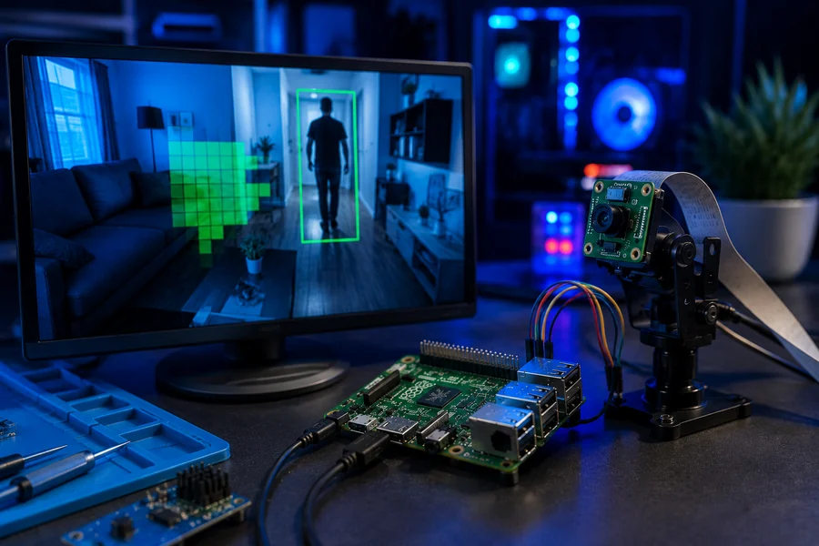
OpenCV Motion Camera
Goal: Use OpenCV to compare camera frames and save a snapshot when real movement is detected.
Printable OpenCV Lab Manual Included
This upgraded OpenCV section now includes a full PDF lab manual with camera setup, OpenCV install commands, camera test steps, motion detection code, tuning guidance, troubleshooting, and upgrade paths.
Easy Build Steps
- Mount the camera so it cannot wobble.
- Test the camera before installing OpenCV.
- Install OpenCV with sudo apt install python3-opencv -y.
- Run a simple camera capture test.
- Run the motion script and tune the threshold.
Install Commands
sudo apt update
sudo apt install python3-pip python3-opencv v4l-utils -y
python3 -c "import cv2; print(cv2.__version__)"
ls /dev/video*
Camera Setup Warning
Power off the Raspberry Pi before inserting or removing a CSI camera ribbon cable. A loose or crooked ribbon cable is one of the fastest ways to turn this project into a troubleshooting mess.
Quick Test
Run the camera test first. If the camera does not work there, OpenCV will not fix it. After the camera works, run the motion script and wave your hand in front of the camera. A snapshot should save into the motion_captures folder.
Upgrade Path
- Send a motion MQTT alert.
- Save snapshots to the Flask dashboard.
- Add date folders for captures.
- Log motion events into SQLite.
- Move the servo pan-tilt mount toward detected movement.