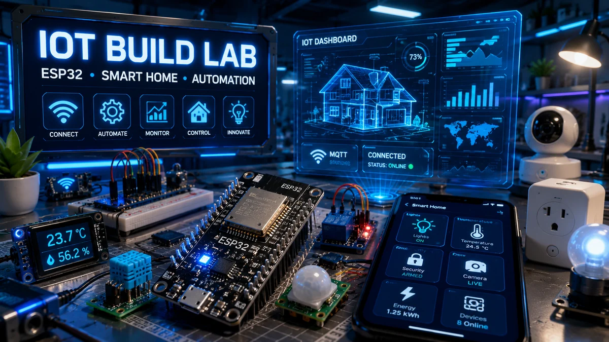
WolfieWeb IoT Command Center
Start here if you want to build real smart devices instead of just reading theory. This hub connects ESP32 projects, MQTT dashboards, Home Assistant ideas, mobile app control, sensor nodes, relay automation, and connected camera builds into one learning path.
Featured ESP32 Learning Paths
Use these as your roadmap. Start with one sensor, prove the wiring, then move into dashboards, automation, phone control, and camera monitoring.
AI Smart Home Hub
Build a practical ESP32 smart home hub with sensors, alerts, relays, and automation logic.
MQTT Sensor Node
Publish sensor data to a broker and learn the backbone of many smart home systems.
Smart Relay Control
Control low-voltage devices safely before moving into more advanced automation.
Connected Camera
Use ESP32-CAM or Raspberry Pi camera setups for monitoring and alerts.
Start building smarter connected devices
IoT is where electronics, sensors, software, and the internet come together. The upgraded version of this page teaches the build process instead of only showing the finished idea.
Start small, test one part at a time, and use the wiring diagrams as your map. Every project below now includes a pin table, parts list, common mistakes, and next-level upgrades.
- Wire sensors and outputs with clearer pin-by-pin guidance.
- Use SVG diagrams that can be opened, printed, or placed inside PDFs.
- Understand MQTT, relay safety, mobile control, and camera setup as systems.
- Build confidence before expanding into full smart-home projects.
What is upgraded
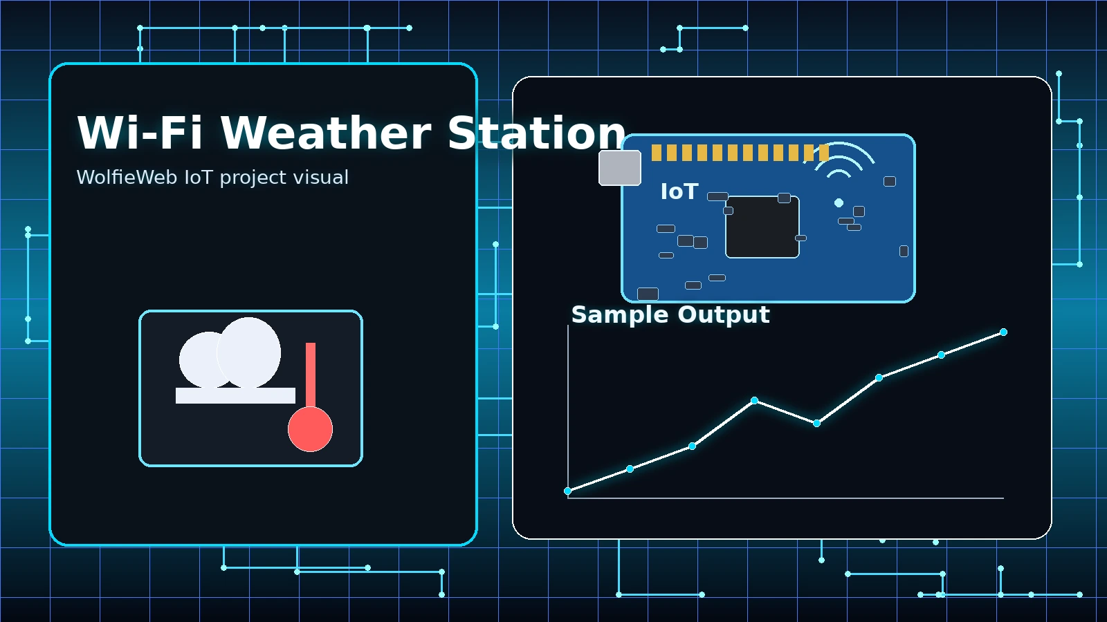
Wi-Fi Weather Station
Build this project one layer at a time: wire the hardware, test the signal, then add the Wi-Fi or network feature. That approach keeps the project understandable instead of turning it into a mystery box.

Build instructions
Parts needed
- ESP32 Dev Board
- DHT22 or DHT11 sensor
- 10k ohm resistor
- Breadboard
- Male-to-male jumper wires
- USB cable
Step-by-step build
- Place the DHT22 sensor across the breadboard gap so each pin has its own row.
- Connect VCC to ESP32 3V3 and GND to ESP32 GND before adding the data line.
- Connect DATA to GPIO4, then place the 10k resistor between VCC and DATA.
- Upload a basic DHT test sketch and confirm serial readings before adding Wi-Fi or dashboard code.
- Only after the readings are stable, add the network publishing or dashboard portion.
Pin mapping
| Board / Source | Connects To | Why It Matters |
|---|---|---|
| ESP32 3V3 | DHT22 VCC | Power the sensor from 3.3V, not 5V. |
| ESP32 GND | DHT22 GND | Common ground is required. |
| ESP32 GPIO4 | DHT22 DATA | Digital data signal. |
| 10k resistor | VCC to DATA | Pull-up keeps data stable. |
Common mistakes
- Using 5V on the sensor when your board expects 3.3V logic.
- Forgetting the 10k pull-up resistor on DATA.
- Reading from the wrong GPIO number in code.
Upgrade ideas
- Send readings to MQTT every 60 seconds.
- Add a small OLED display.
- Log data to a web dashboard.
Video not loading? Watch the tutorial on YouTube.
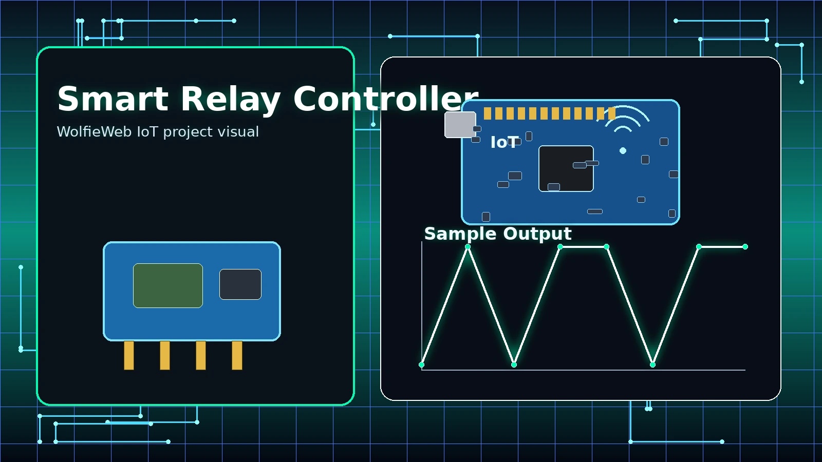
Smart Relay Controller
Build this project one layer at a time: wire the hardware, test the signal, then add the Wi-Fi or network feature. That approach keeps the project understandable instead of turning it into a mystery box.

Build instructions
Parts needed
- ESP32 Dev Board
- 1-channel 3.3V-compatible relay module
- Low-voltage LED strip or small DC load
- External low-voltage power supply
- Breadboard/jumpers
- USB cable
Step-by-step build
- Start with a low-voltage DC load only; do not begin with wall voltage.
- Wire relay VCC and GND to the control side first.
- Connect relay IN to GPIO5 and test whether the relay clicks with a simple blink-style sketch.
- Wire the low-voltage load through COM and NO so it only powers when the relay closes.
- Test short ON/OFF cycles and confirm the load switches cleanly.
Pin mapping
| Board / Source | Connects To | Why It Matters |
|---|---|---|
| ESP32 3V3 or VIN | Relay VCC | Match the relay module requirements. |
| ESP32 GND | Relay GND | Common ground for control side. |
| ESP32 GPIO5 | Relay IN | GPIO toggles relay state. |
| Load + | Relay COM/NO | Use low voltage while learning. |
Common mistakes
- Working with AC mains before understanding relay wiring.
- Buying a 5V relay that does not trigger reliably from 3.3V GPIO.
- Mixing load power and ESP32 power incorrectly.
Upgrade ideas
- Add a web button for ON/OFF control.
- Add a physical override button.
- Add MQTT commands such as home/relay/set.
Video not loading? Watch the tutorial on YouTube.
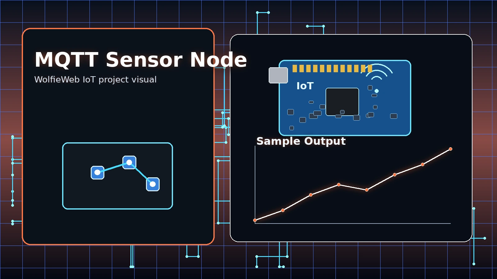
MQTT Sensor Node
Build this project one layer at a time: wire the hardware, test the signal, then add the Wi-Fi or network feature. That approach keeps the project understandable instead of turning it into a mystery box.

Build instructions
Parts needed
- ESP32 Dev Board
- DHT22 sensor
- 10k ohm resistor
- Breadboard/jumpers
- MQTT broker such as Mosquitto
- Wi-Fi network
Step-by-step build
- Build and test the sensor wiring first, exactly like the weather station project.
- Install or choose an MQTT broker and confirm the broker IP address.
- Flash code that connects to Wi-Fi, then connects to the MQTT broker.
- Publish test messages before publishing sensor values.
- Subscribe from a dashboard or MQTT client and verify the data appears.
Pin mapping
| Board / Source | Connects To | Why It Matters |
|---|---|---|
| ESP32 3V3 | DHT22 VCC | Sensor power. |
| ESP32 GND | DHT22 GND | Common ground. |
| ESP32 GPIO4 | DHT22 DATA | Sensor input. |
| MQTT Topic | wolfieweb/iot/weather | Published readings go here. |
Common mistakes
- Wrong broker IP address or port.
- Using the wrong topic name between publisher and subscriber.
- Publishing too fast and flooding the broker.
Upgrade ideas
- Add JSON payloads for temperature and humidity.
- Add retained status messages.
- Use Home Assistant or Node-RED as a dashboard.
Video not loading? Watch the tutorial on YouTube.
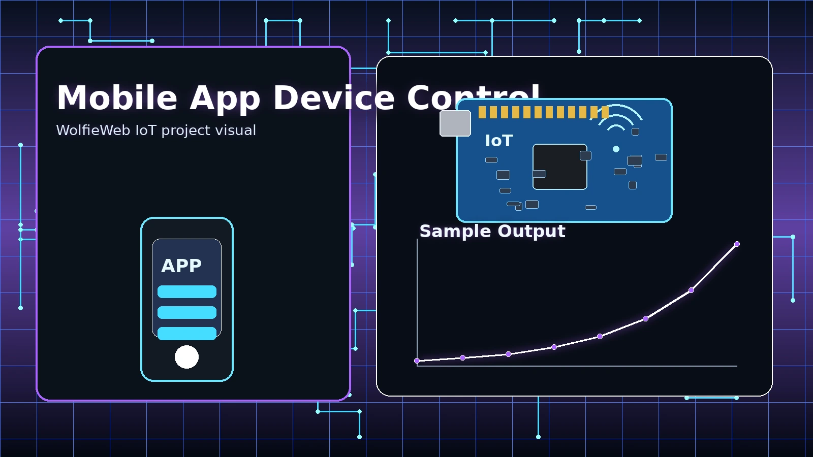
Mobile App Device Control
Build this project one layer at a time: wire the hardware, test the signal, then add the Wi-Fi or network feature. That approach keeps the project understandable instead of turning it into a mystery box.

Build instructions
Parts needed
- ESP32 Dev Board
- LED or relay test output
- 220 ohm resistor for LED
- Breadboard/jumpers
- Mobile control app or simple web dashboard
- Wi-Fi network
Step-by-step build
- Wire a simple LED output first so testing is safe and obvious.
- Upload code that turns the LED on and off from a local command.
- Connect the ESP32 to your Wi-Fi network and print the IP address.
- Use your phone on the same Wi-Fi network to open the control screen or send commands.
- After the LED works, replace it with a relay or larger controlled output.
Pin mapping
| Board / Source | Connects To | Why It Matters |
|---|---|---|
| ESP32 GPIO2 | LED Anode through 220 ohm resistor | Test output. |
| LED Cathode | ESP32 GND | Completes circuit. |
| Phone App | ESP32 Web/MQTT endpoint | Sends command. |
| ESP32 Wi-Fi | Router | Network path. |
Common mistakes
- Phone and ESP32 on different networks.
- Router blocking local device discovery.
- Trying relay control before proving simple LED control.
Upgrade ideas
- Add a better mobile UI with large buttons.
- Add state feedback so the app shows ON/OFF correctly.
- Add password protection before exposing anything outside the home network.
Video not loading? Watch the tutorial on YouTube.
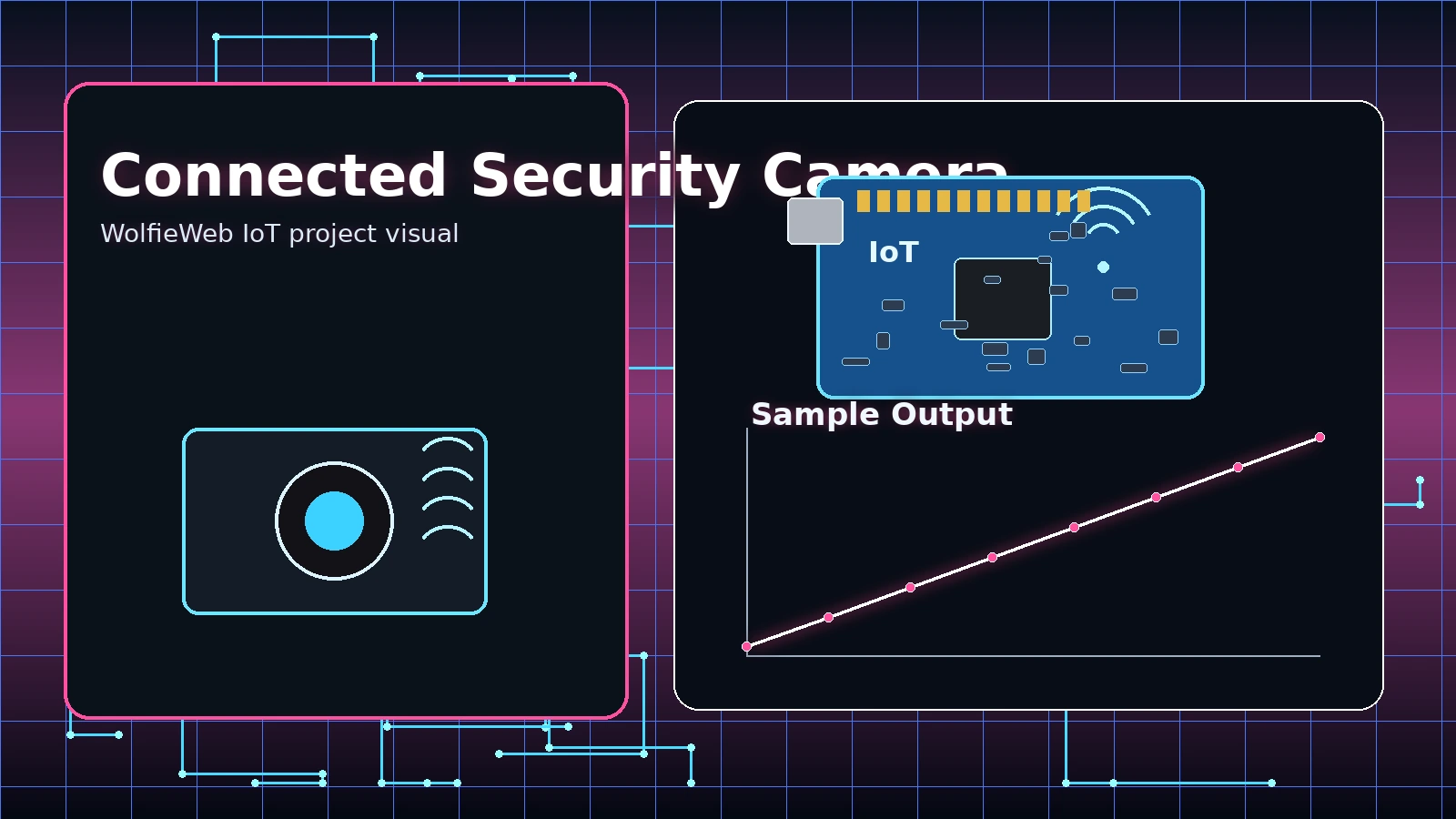
Connected Security Camera
Build this project one layer at a time: wire the hardware, test the signal, then add the Wi-Fi or network feature. That approach keeps the project understandable instead of turning it into a mystery box.

Build instructions
Parts needed
- ESP32-CAM or Raspberry Pi camera setup
- FTDI programmer for ESP32-CAM
- PIR motion sensor optional
- Stable 5V power supply
- Jumper wires
- MicroSD card optional
Step-by-step build
- Use a stable 5V supply; camera boards brown out easily with weak USB power.
- Wire FTDI programmer TX/RX crossed to the ESP32-CAM serial pins.
- Hold GPIO0 to GND only while flashing firmware.
- After flashing, remove GPIO0 from GND and reboot the board.
- Open the printed camera URL from a browser on the same network.
Pin mapping
| Board / Source | Connects To | Why It Matters |
|---|---|---|
| 5V Supply | ESP32-CAM 5V | Camera needs stable power. |
| GND | ESP32-CAM GND | Common ground. |
| FTDI TX/RX | ESP32-CAM U0R/U0T | Used for programming. |
| GPIO0 to GND | Flash mode only | Remove after flashing. |
Common mistakes
- Leaving GPIO0 grounded after flashing.
- Weak power supply causing restarts.
- Expecting camera stream to work outside the home network without router/security setup.
Upgrade ideas
- Add PIR-triggered snapshots.
- Save images to microSD.
- Send motion alerts to a dashboard or phone.
Video not loading? Watch the tutorial on YouTube.
Printable IoT lab manual included
The updated PDF matches this page: wiring diagrams, pin maps, parts lists, beginner steps, common mistakes, and upgrade ideas.
Get the IoT Lab Manual PDFQuick answers before you start
What board should you start with?
ESP32 is usually the best first choice because it has Wi-Fi, Bluetooth, strong community support, and enough power for most beginner-to-intermediate IoT builds.
What should you test first?
Test power and ground first, then one signal wire, then code, then network features. Do not stack problems.
What causes most beginner problems?
Weak power, messy wiring, missing common ground, wrong GPIO number, and adding Wi-Fi before the circuit works.