WolfieWeb Raspberry Pi Lab
Beginner Friendly Build Guides

Simple Raspberry Pi Tutorials With Real Instructions

These projects are meant to be finished, not just admired. Each tutorial now gives you the exact goal, parts, wiring, build steps, code, testing checks, mistakes to avoid, and a small upgrade path.

Start with the LED. Then add button input, sensors, camera work, and motion detection. That path teaches the basics in the right order.

Raspberry Pi beginner electronics tutorials on a workbench
๐ŸŽฎ WolfieWeb Build Quest

Step 1 of 5: Raspberry Pi Basics

Progress: loading...
๐Ÿ“ Pi Starter ๐Ÿ”ง Robot Builder โšก Wiring Rookie ๐Ÿ”Œ Arduino Maker ๐ŸŒ IoT Explorer

Pick a Tutorial

Go in order if you are new. Skipping around is fine, but the early projects teach the pin numbering and wiring habits you need later.

Guided Learning Path

Finish These in Order

This page now works like a mini-course. Each lesson builds on the last one, so beginners do not get dumped into random parts and confusing wiring.

Raspberry Pi GPIO LED wiring on breadboard
Tutorial 1 ยท Beginner
Step 1 of 5 ยท Learn GPIO output

GPIO LED Output

Goal: Make an LED blink from Python so you understand GPIO output, resistor safety, and the difference between physical pin numbers and GPIO numbers.

What should happen: The LED turns on for one second, turns off for one second, and repeats.

Parts Needed

  • Raspberry Pi with Raspberry Pi OS
  • Breadboard
  • 1 LED
  • 220ฮฉ or 330ฮฉ resistor
  • 2 jumper wires

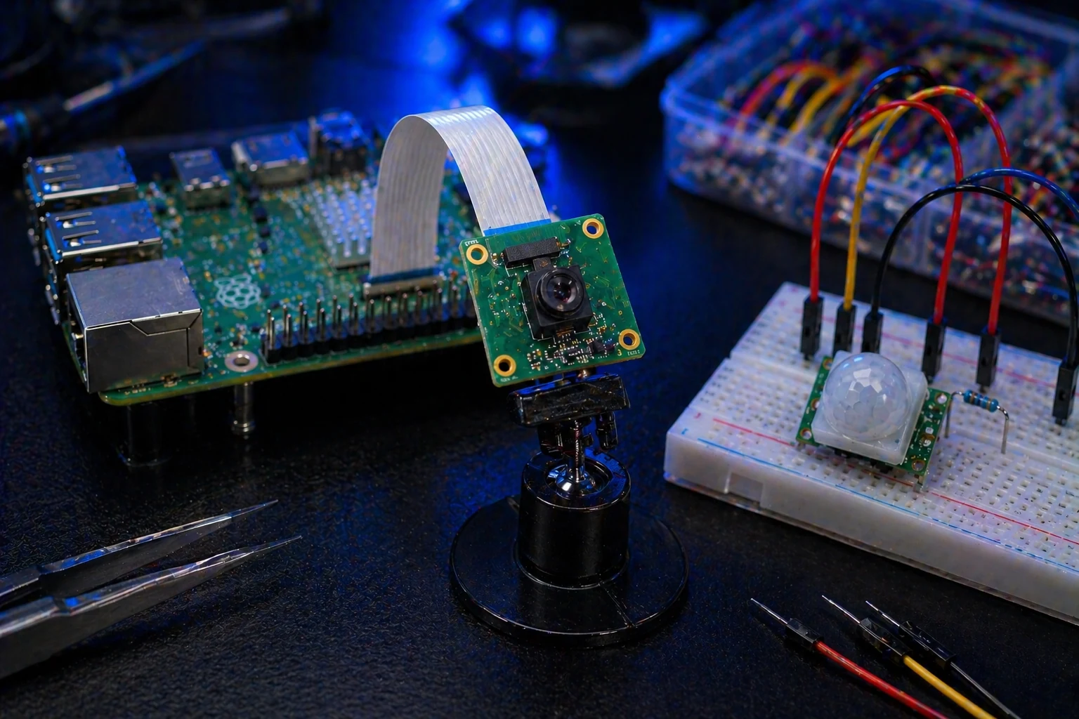
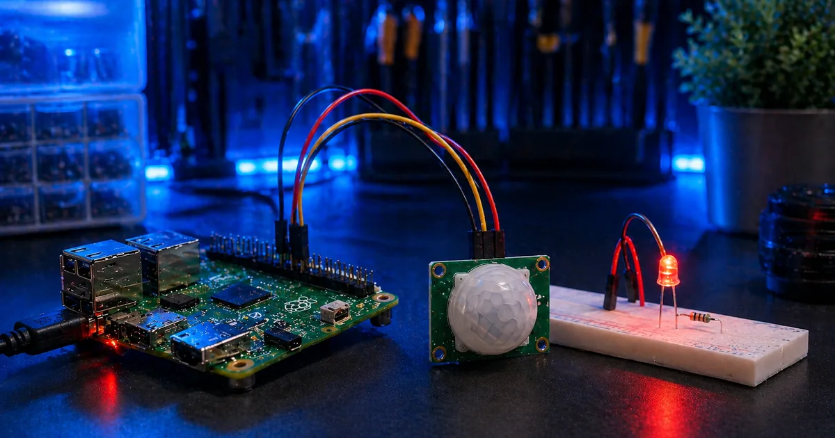
Helpful Starter Parts

A basic Raspberry Pi electronics kit with LEDs, resistors, jumper wires, and a breadboard will cover this first lesson and several lessons after it.

View Starter Parts โ†’

Wiring Steps

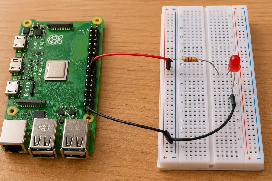
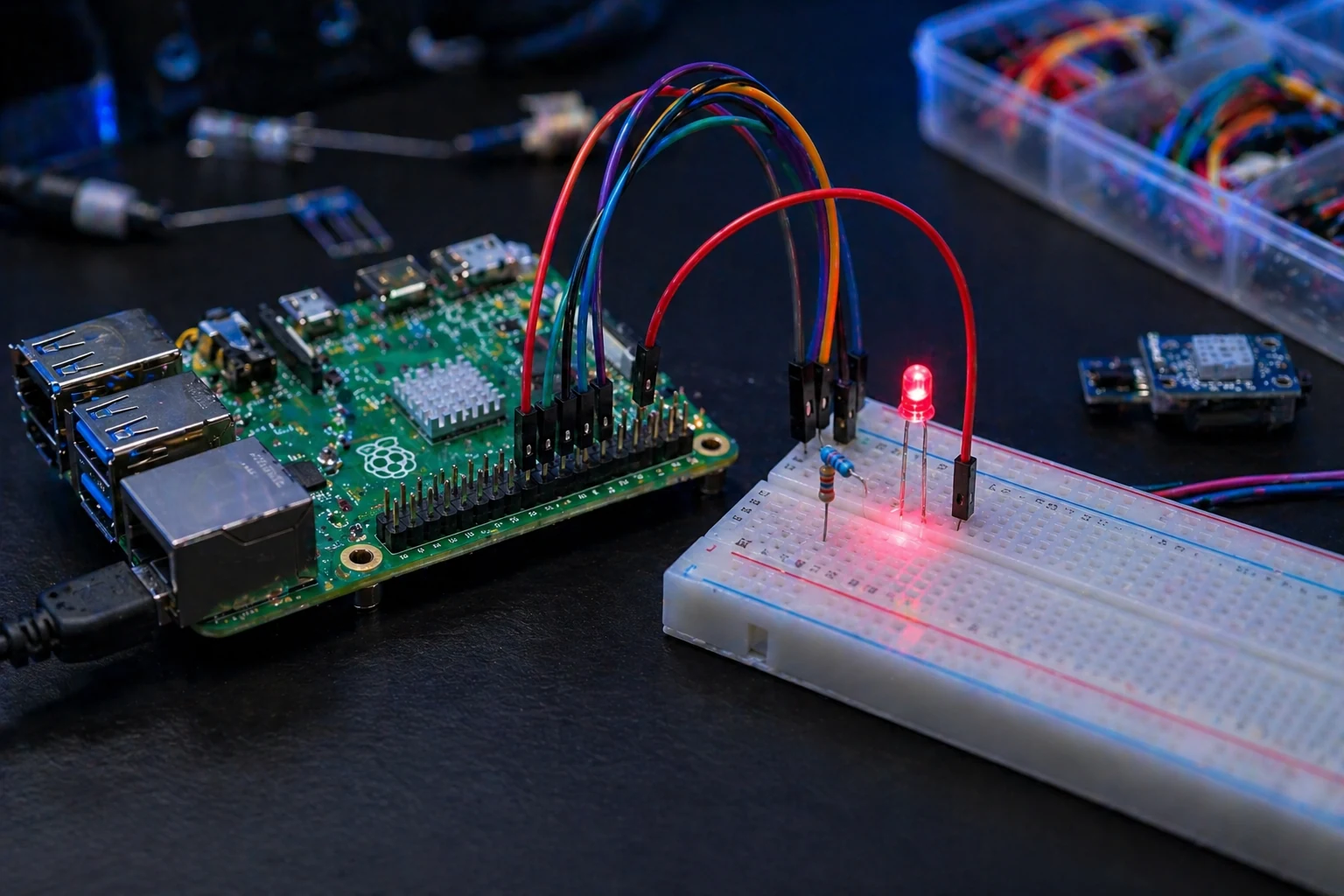
  1. Connect GPIO17, physical pin 11, to one side of the resistor.
  2. Connect the other side of the resistor to the long LED leg.
  3. Connect the short LED leg to GND, physical pin 6.
  4. Do not skip the resistor. That is how LEDs get burned out.

Easy Build Steps

  1. Shut the Pi down before wiring.
  2. Build the circuit on the breadboard.
  3. Boot the Pi and open Terminal.
  4. Create led_blink.py.
  5. Paste the code and run python3 led_blink.py.

Mistakes to Avoid

  • Using physical pin 17 instead of GPIO17.
  • Putting the LED in backward.
  • Forgetting the resistor.
  • Loose jumper wires that look connected but are not.

Starter Code

from gpiozero import LED
from time import sleep

led = LED(17)

while True:
    led.on()
    sleep(1)
    led.off()
    sleep(1)
Close-up of LED resistor and GPIO jumper wiring

Suggested instruction image: close-up view of GPIO17 wire, resistor, LED legs, and ground wire.

Quick Test

Run the code. If the LED blinks, the wiring and Python setup are good. If it stays dark, flip the LED first. If that fails, move the jumper wire back to GPIO17 and check the ground pin.

Upgrade: Add two more LEDs and make a simple traffic light.

โœ” Micro-win: You just controlled real hardware with Python.
Raspberry Pi push button input wiring on breadboard
Tutorial 2 ยท Beginner
Step 2 of 5 ยท Learn button input

Push Button Input

Goal: Read a button press from Python. This teaches input, pull-up resistors, and how the Pi reacts to a real-world action.

What should happen: Press the button and the terminal prints a message. Release it and the program waits for the next press.

Parts Needed

  • Raspberry Pi
  • Breadboard
  • Push button
  • 2 jumper wires

Helpful Button Parts

Small tactile buttons are cheap, useful, and perfect for input projects, menus, robot controls, and simple trigger systems.

View Button Parts โ†’

Wiring Steps

  1. Place the button across the center gap of the breadboard.
  2. Connect one button leg to GPIO2, physical pin 3.
  3. Connect the opposite button leg to GND.
  4. The code uses the Piโ€™s internal pull-up, so no extra resistor is needed for this version.

Easy Build Steps

  1. Wire the button while the Pi is powered off.
  2. Boot the Pi and open Terminal.
  3. Create button_test.py.
  4. Run the file and press the button.
  5. Confirm the terminal prints the message only when pressed.

Mistakes to Avoid

  • Putting both wires on the same side of the button.
  • Using a GPIO pin already used by another project.
  • Not seating the button across the breadboard gap.

Starter Code

from gpiozero import Button
from signal import pause

button = Button(2)

def pressed():
    print("Button pressed!")

button.when_pressed = pressed

pause()
Close-up of push button wiring connected to Raspberry Pi GPIO and ground

Suggested instruction image: top-down button wiring showing the breadboard gap clearly.

Quick Test

Press the button several times. The message should appear once per press. If it spams messages or never triggers, the button is probably rotated wrong or both wires are on the wrong legs.

Upgrade: Use the button to turn the LED from Tutorial 1 on and off.

โœ” Micro-win: You just made the Pi respond to a physical button press.
Raspberry Pi temperature sensor tutorial wiring
Tutorial 3 ยท Beginner Plus
Step 3 of 5 ยท Read sensor data

Temperature Sensor Monitor

Goal: Read temperature data from a sensor and print it in the terminal. This moves the learner from simple input/output into real measurements.

What should happen: The terminal prints updated temperature readings every few seconds.

Parts Needed

  • Raspberry Pi
  • DHT11 or DHT22 temperature sensor module
  • Breadboard
  • Jumper wires

Helpful Sensor Parts

A DHT11 or DHT22 module gives beginners a simple way to start logging real-world temperature and humidity data.

View Sensor Parts โ†’

Wiring Steps

  1. Connect sensor VCC to 3.3V.
  2. Connect sensor GND to GND.
  3. Connect sensor DATA to GPIO4, physical pin 7.
  4. Check your exact sensor label because some modules swap pin order.

Easy Build Steps

  1. Wire the sensor while the Pi is off.
  2. Boot the Pi and install the sensor library.
  3. Create temp_monitor.py.
  4. Paste the code and run it.
  5. Let it run for a full minute to confirm stable readings.

Mistakes to Avoid

  • Using 5V when your sensor/module expects 3.3V logic.
  • Mixing up VCC, DATA, and GND.
  • Expecting cheap sensors to read perfectly every time.

Starter Code

import time
import board
import adafruit_dht

sensor = adafruit_dht.DHT11(board.D4)

while True:
    try:
        temp_c = sensor.temperature
        humidity = sensor.humidity
        print(f"Temp: {temp_c}C  Humidity: {humidity}%")
    except RuntimeError:
        print("Sensor read error. Trying again...")
    time.sleep(3)
Close-up of Raspberry Pi temperature sensor wiring with labeled sensor pins

Suggested instruction image: sensor close-up with visible VCC, DATA, and GND routing.

Quick Test

Hold your hand near the sensor for a few seconds. The temperature should rise slightly. If the reading never changes or always errors, check the DATA pin and the sensor model in the code.

Upgrade: Save readings to a CSV file or show them on a small web dashboard.

โœ” Micro-win: You just turned the Pi into a basic sensor monitor.
Raspberry Pi camera timelapse setup with ribbon cable
Tutorial 4 ยท Intermediate
Step 4 of 5 ยท Capture images

Camera Timelapse

Goal: Capture images at fixed intervals and save them in a folder. This teaches camera setup, file naming, and basic automation.

What should happen: The Pi saves a new photo every ten seconds.

Parts Needed

  • Raspberry Pi
  • Raspberry Pi Camera Module
  • Camera ribbon cable
  • Stable power supply

Helpful Camera Parts

A Raspberry Pi camera module and a stable power supply make this project much easier. Weak power causes weird camera failures.

View Camera Parts โ†’

Connection Steps

  1. Shut down and unplug the Pi.
  2. Open the camera connector latch gently.
  3. Insert the ribbon cable straight and fully.
  4. Close the latch and avoid bending the cable sharply.

Easy Build Steps

  1. Connect the camera.
  2. Boot the Pi and confirm camera support.
  3. Create a folder named timelapse.
  4. Create timelapse.py.
  5. Run the script and check the output folder.

Mistakes to Avoid

  • Connecting the ribbon cable backward.
  • Trying to test the camera in a dark room.
  • Using a weak power supply that causes random crashes.

Starter Code

from picamera2 import Picamera2
from time import sleep
from datetime import datetime
import os

folder = "timelapse"
os.makedirs(folder, exist_ok=True)

camera = Picamera2()
camera.start()
sleep(2)

for shot in range(10):
    filename = datetime.now().strftime("%Y-%m-%d_%H-%M-%S.jpg")
    path = os.path.join(folder, filename)
    camera.capture_file(path)
    print("Saved:", path)
    sleep(10)
Close-up of Raspberry Pi camera ribbon cable installed correctly

Suggested instruction image: close-up of the camera ribbon cable seated in the connector.

Quick Test

Open the timelapse folder. You should see a row of timestamped images. If no images appear, test the camera first before changing the script.

Upgrade: Turn the saved images into a video or trigger the camera only when motion is detected.

โœ” Micro-win: You just made the Pi capture images automatically.
Raspberry Pi PIR motion sensor wiring tutorial
Tutorial 5 ยท Beginner Plus
Step 5 of 5 ยท Detect motion

PIR Motion Sensor Alert

Goal: Detect motion with a PIR sensor and print an alert. This is one of the easiest ways to make the Pi react to the real world.

What should happen: Move in front of the sensor and the terminal prints a motion alert.

Parts Needed

  • Raspberry Pi
  • PIR motion sensor module
  • 3 jumper wires
  • Breadboard optional

Helpful Motion Parts

A PIR sensor module is one of the easiest upgrades for alarms, smart rooms, and camera-triggered projects.

View PIR Parts โ†’

Wiring Steps

  1. Connect PIR VCC to 5V if your PIR module requires it.
  2. Connect PIR GND to Pi GND.
  3. Connect PIR OUT to GPIO14, physical pin 8.
  4. Give the PIR sensor 30 to 60 seconds to settle after power-up.

Easy Build Steps

  1. Wire the PIR sensor.
  2. Boot the Pi and open Terminal.
  3. Create motion_alert.py.
  4. Run the script and wait for the sensor to settle.
  5. Wave your hand in front of the sensor.

Mistakes to Avoid

  • Testing immediately before the PIR has settled.
  • Pointing the sensor at a fan, window, or heat source.
  • Using the wrong OUT pin in code.

Starter Code

from gpiozero import MotionSensor
from signal import pause

pir = MotionSensor(14)

def motion_seen():
    print("Motion detected!")

pir.when_motion = motion_seen

pause()
Close-up of PIR motion sensor connected to Raspberry Pi

Suggested instruction image: close-up of PIR module with VCC, OUT, and GND wires visible.

Quick Test

Wait one minute after boot, then move across the sensorโ€™s view. If it triggers constantly, aim it away from windows, vents, and heat sources.

Upgrade: Combine this with the camera tutorial to save a photo only when motion is detected.

โœ” Micro-win: You just built the foundation for motion-triggered smart projects.
Keep Users Moving

Ready for Real Projects?

Once the basics are working, combine them. LEDs become status lights, buttons become controls, sensors become triggers, and the camera becomes proof that something happened.

Smart Motion Camera

Use the PIR sensor to trigger the camera and save a photo only when motion is detected.

Review Motion Lesson โ†’

Room Monitor

Use the temperature sensor to track room conditions and later save the readings to a CSV file.

Review Sensor Lesson โ†’

Beginner Robot Controls

Use buttons, LEDs, and sensors as the control foundation for later robot and IoT builds.

Explore More Builds โ†’

Share This Tutorial Page

Send this page to someone starting with Raspberry Pi. It is built to get beginners moving without dumping them into confusing random videos.

Learning Path Copy Link
NEXT QUEST

Keep Building

You finished this stop in the WolfieWeb build path. Keep going while the wiring and logic are still fresh.

โžก๏ธ Next: Build Your First Robot